Radon Mitigation using a French Drain
by Doug
(Ridgway, CO)

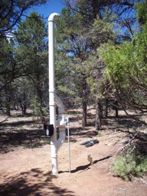
Radon Vent Discharge 10' above Grade
Three or four years ago, I measured the radon levels in my newly constructed house with a lab test kit and it measured 19pCi/L. I stuck my head in the sand then and ignored it because I thought it was a big deal to fix. Recently, I read that one can use the French drain that is placed around my foundation to suck out the radon, so I thought a system designed around that would be much easier. Otherwise, I would have had to drill a hole in my slab and then another hole in my concrete basement wall to have an exit for the pipe(I have no attic and the house is open floor plan so there was no real easy way to go up inside the house). I also didn't want an unsightly fan on the outside of the house, so the French drain design seemed to be ideal.
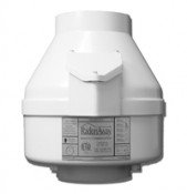
The concept of using the drain didn't seemed to be sound to me though since the drain is on the outside of the stem wall - the fan would have to suck air from under the footer, up the inside of the stem wall and then under the slab. I was leery of that being able to happen. But I set up a temporary installation by just putting an elbow at the day light end of the drain and put the fan on top (with a long extension cord powering it!). To my amazement, the readings started at about 14 using a Pro 3 radon monitor and went to 2.0 in 6-7 days. That told me it would work, so I installed it permanently. I thought I would have to move the fan closer to the house than the 150' I tested it at but since it tested good there, I just installed it near the end among the trees. I was also concerned about the unsightly look and the potential for hearing the fan noise at night, so that was perfect.
As you can see from the picture, my pipe design was a bit different as well. I was hoping that the 4" PVC pipe would provide enough structure to hold the system vertically without the need for guy wires so I decided to modify the condensation system a bit to make the structure more rigid than the rubber fan couplers would provide. Now, condensation falls through the vertical pipe, but then hits a rubber disk I placed inside the top Wye fitting (I made an annular ring out of plastic that I put in first to support the disk). The disk has a 3/32" hole in the center where the water is sucked through and falls to the bottom. I left the top stack loose(not glued) to allow for inspection of that disk. The condensation collection seems to work OK.
At the base of the system, I installed a PVC "T" fitting in the corrugated drain pipe that went horizontally to another "T" fitting. One end of that fitting went into the ground and the other end pointed upward where the fan would go. I concreted that fitting in the ground to provide structure.
I also needed a backwater flapper valve at the end of the drain pipe in order to allow drainage water to exit the system. You can see the grey valve in the background in the picture. I think that works OK but may have a tiny vacuum leak.
The black box in the pictures house the manometer and a remote sensor system to monitor the vacuum from the house. I got a vacuum valve used on furnaces that senses .47"WC and connected the normally open contacts to the battery wires inside an outdoor wireless temperature sensor. So now, I know that when an outdoor temperature is displayed in the house, the vacuum is at least .47"WC and the fan is working. Otherwise, the temperature is not displayed and I know something is wrong.
Val was a great help to me - I'm glad I found him!
Comments for Radon Mitigation using a French Drain
|
||
|
||
|
||
|
||
|
||
|
||


